|
|
Measurement of the electrical conductivity / resistivity of silicate glass melts
Alexander Fluegel, 2005, info@glassproperties.com
Click here for electrical conductivity calculation and definitions
Introduction
The
electrical resistivity ![]() (rho) is defined through
Equation (1), with A being the surface area of the electrodes, and L being the
distance between them. According to Ohm’s law the resistance R is the quotient
of the potential difference E in Volts over the electric current I in Amperes:
R = E / I. The unit of the resistivity or specific resistance is
(rho) is defined through
Equation (1), with A being the surface area of the electrodes, and L being the
distance between them. According to Ohm’s law the resistance R is the quotient
of the potential difference E in Volts over the electric current I in Amperes:
R = E / I. The unit of the resistivity or specific resistance is ![]()
![]() m:
m:
|
|
Eq. (1) |
The
conductivity or specific conductance ![]() is the reciprocal of the
resistivity,
is the reciprocal of the
resistivity, ![]() = 1/
= 1/ ![]() , with the unit (
, with the unit (![]()
![]() m)-1
or S/m (S = Siemens).
m)-1
or S/m (S = Siemens).
In glass melts the electric current is predominantly transported through mobile ions. Other conducting species are not considered here.
For accurate measurements of the electrical resistivity of glass melts several details have to be considered: At the beginning of measurements, relatively low potential barriers occur for some conducting ions due to a broad potential barrier distribution based on polarization effects in the electric field ("ionic polarization"). The mentioned conducting ions are able to surmount the low barriers easily and the measured resistivity is relatively low. After a while higher potential barriers appear for all conducting ions and the resistivity increases. The constant steady-state resistivity is reached [1, 2].
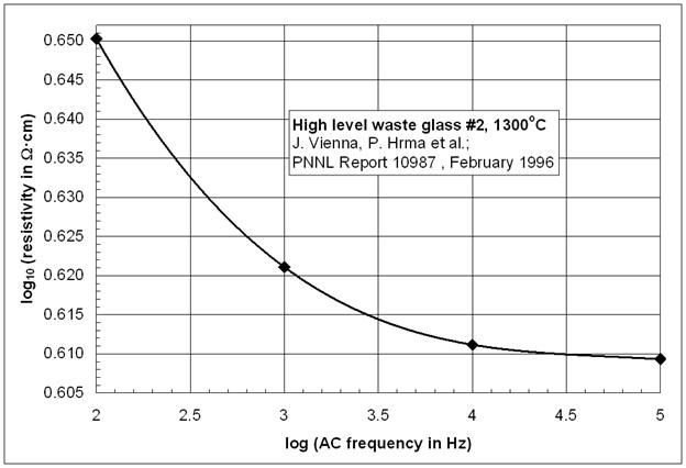
The conducting ions in the glass melt are discharged at the electrode surfaces and insulating layers are formed ("electrode polarization"). The electrode polarization increases with decreasing AC frequency, i.e., the melt resistivity appears to increase as well with decreasing AC frequency as seen in the Figure below. Therefore, direct current (DC) resistivity measurements on glass melts and solid glass are not recommended [3].
Electrode polarization
For obtaining resistivity data with reduced or negligible influence of electrode polarization effects, it is beneficial to record the electrical resistivity over various frequencies and to extrapolate to a constant resistivity value in the frequency-independent region. However, the electrode polarization can never be totally avoided since ions are the predominantly conducting species in the glass melt, and electrons are the conducting species in the electrodes, i.e., surface reactions must always take place. Therefore, the electrode material influences the electrode polarization [4].
At low temperatures the electrode polarization may be eliminated through the use of "reversible electrodes", i.e., electrodes that contain the conducting ions in the same activity as the glass. The electrodes may consist of pure alkali metals, alkali metal alloys (e.g. amalgam, tin alloys, etc.), or alkali salts. Reversible electrodes can not be used at glass melting temperatures due to chemical instability.
For glass melts, platinum electrodes are used most frequently in research, while molybdenum or tin oxide electrodes are used for industrial applications. The polarization-free resistivity can be determined through impedance spectroscopy described below with high accuracy.
With increasing AC frequency capacitative reactance effects start to interfere with the glass resistance, which becomes increasingly important if the glass resistance is high. On the other hand, if the glass resistance is low inductive reactance effects interfere with increasing AC frequency. The interplay between resistance, capacitive reactance, and inductive reactance can be expressed through Equation (2). It must be noted, however, that Equation (2) is only valid if resistance, capacitive reactance, and inductive reactance are in line circuit, which is only seldom appropriate for practical application:
|
Z = R + j |
Eq. (2) |
|
Z |
= Impedance |
|
R |
= Resistance |
|
XL |
= Inductive Reactance |
|
XC |
= Capacitive Reactance |
|
j2 |
= -1 |
The resistivity of the glass examined can be derived from the impedance-frequency spectrum through assuming equivalent circuits as described for example by Ravagnani et al. [5], Keding et al. [6], and Schiefelbein et al. [7].
In many publications concerning the electrical resistivity of glass melts XL and XC are assumed to be negligible for measuring R, i.e., the absolute of the impedance is set equal to the resistance. This may be a good estimation for common glass melts at measurement frequencies of about 3-50 kHz [8], i.e., if the resistance is independent of the AC frequency. Still, it must be stated that proper impedance spectroscopy does allow the most reliable resistivity measurements of glasses, because the electrode polarization can be compensated most effectively, with the result that phase separation [5], crystallization [6], and the glass transition temperature Tg can be detected.
The shape of the electric field during electrical resistivity measurements is reported to influence the result [7], therefore, a well-defined cell construction [8] is superior in principle to platinum-wire electrode techniques [2, 9, 12, 13, 17]. A defined shape of the electric field between the electrodes does allow calibration-free measurements [5, 6, 7, 8].
The thermal expansion of the electrodes, crucible, and the glass melt need to be compensated for some measurement techniques [9], as well as resistance changes of the electrodes and wiring at high furnace temperatures. In addition, the surface tension and wetting between the glass melt and electrodes can influence the result. Finally, an inhomogeneous temperature distribution at high furnace temperatures can lead to incorrect temperature readings and convection currents of the glass melt, especially if one of the electrodes is the platinum crucible that contains the melt.
The applied voltage during resistivity measurements of glass melts is not reported in several papers unfortunately, despite its influence on the resistivity at high voltages due to various ionization potentials of the conducting ions [10, 11]. Schiefelbein et al. recommends 30-60 mV [7], because those potentials activate the mobile ions similarly to the thermal excitation in solid glass (E = 3kT/2).
Electrical resistivity measurement techniques
Several techniques are applied for measuring the electrical resistivity of glass melts that may be classified into three groups: 1) The absolute, calibration-free methods; 2) The methods based on low-temperature calibration using solid glass; and 3) The methods based on room temperature calibration using aqueous solutions.
The absolute method was introduced by Baucke et al. [8]: Two parallel electrodes are immersed into the glass melt and the resistivity can be determined directly according to Equation (1). This straightforward approach allows very reliable measurements, and it does not require calibration using reference materials at lower temperatures. It is possible to use various electrode shapes for the absolute technique [5, 6, 7, 8].
According the methods by Mach [12], Mazurina [17], Mazurin and Prokhorenko [2], and Startsev [13] a "crucible constant" or "geometric factor" is determined using platinum wire electrodes at temperatures below the glass transition Tg through the measurement of the resistivity of a glass disk by the absolute method, and through measurement of the same glass in the crucible (or alternative setup) used for high temperature measurements after cooling. The "crucible constant" or "geometric factor" equals the quotient L/A in Equation (1). It is assumed that the measured glass shows a comparable behavior at low and high temperatures, e.g., crystallization, phase separation, surface tension, wetting behavior, dielectric constant, and the shape of the electric field between the electrodes. Thermal expansion effects of the glass sample and equipment have to be considered and compensated.
The measurement technique suggested by Tickle [9] was developed on the basis of room temperature standard reference materials, in general potassium chloride (KCl) solutions in water. The "crucible constant" or "geometric factor" (= L/A in Equation (1)) is calibrated using platinum wire electrodes in KCl solution. It is assumed that the glass melt at elevated temperature shows a behavior comparable to KCl solution at room temperature, e.g., surface tension, wetting behavior, dielectric constant, and the shape of the electric field between the electrodes. During measurements on glass melts thermal expansion effects have to be compensated precisely. Kim et al. [14] applied glass melt resistivity data by Tickle as "standard" for calibrating his "crucible constant". Despite of the many assumptions and extrapolations required, the method by Tickle was used for establishing the glass melt electrical resistivity standard NIST SRM 1414 [15] (currently retracted), which, in turn, was used for calibration in other publications [16]. It future the definition of a new glass melt electrical resistivity standard is required that has a more common composition than the lead silicate SRM 1414, and where the measurements are based on a reliable technique and good documentation (e.g. including the measurement frequencies).
It becomes clear that the absolute method by Baucke et al. [8] is based on much less assumptions and approximations than the other techniques, therefore it can be considered most reliable. For the absolute method impedance measurements should be performed [7]. The reliability of the methods according to Mach [2, 12, 13, 17] and Tickle [9, 14, 15, 16] are both less precise. For common glasses where no crystallization and phase separation are observed during cooling below the transformation range, the methods according to Mach [2, 9, 12, 17] may be regarded superior to methods according to Tickle [8, 13, 14, 15]. However, the methods according to Mach should not be applied for measuring special glass compositions such as selected E-glasses and other borosilicates that may crystallize or phase separate.
For industrial use electrode polarization effects have to be considered, as in most scientific publications the polarization-free resistivity at elevated measurement frequencies is reported (see above), but for industrial applications a low frequency of 50 Hz and molybdenum or tin oxide electrodes might be employed. Furthermore, the applied voltage in scientific publication is often below 1 Volt; at higher voltages the resistivity of glass melts might decrease significantly due to ionization of glass forming and intermediate oxides, e.g., SiO2, B2O3, Al2O3, etc.
Establishment of a standardized high-accuracy procedure required
Electrical resistivity measurements of glass melts are not well established yet in scientific research; scattering of the published experimental data and systematic errors can be expected. In future it would be beneficial to create a standardized method for measuring the electrical resistivity of glass melts with high accuracy. The procedure described by Schiefelbein et al. [7] appears most promising.
References
[1] J. Stanek: "Electric Melting of Glass"; Elsevier Scientific Publishing, Amsterdam 1977
[2] O. V. Mazurin, O. A. Prokhorenko: "Electrical conductivity of glass melts"; Chapter 9 in: "Handbook on the Properties of Glass-Forming Melts" ed. by D. L. Pye, I. Joseph, A. Montenaro; CRC Press, Boca Raton, Florida, 2005
[3] ASTM C657-93: "Standard Test Method for D-C Volume Resistivity of Glass", 2003
[4] C. J. Leo, B. V. R. Chowdari, G. V. Subba Rao, J. L. Souquet: "Lithium conducting glass ceramic with Nasicon structure"; Materials Research Bulletin, 2002, vol. 37, p 1419-1430
http://dx.doi.org/10.1016/S0025-5408(02)00793-6 (0.5 MB)
[5] Ch. Ravagnani, R. Keding, Ch. Rüssel: "High temperature impedance spectroscopy of homogeneous and phase separated melts and glasses of the composition 48.5 SiO2 - 48.5 B2O3 - 3 Na2O"; J. Non-Cryst. Solids, 2003, vol. 328, p 164-173
http://dx.doi.org/10.1016/S0022-3093(03)00475-7 (0.3 MB)
[6] R. Keding, D. Tauch, Ch. Rüssel: "Electrical impedance determination of phase transitions in glasses and melts"; J. Non-Cryst. Solids, 2004, vol. 348, p 123-130
http://dx.doi.org/10.1016/j.jnoncrysol.2004.08.137 (0.4 MB)
[7] S. L. Schiefelbein, N. A. Fried, K. G. Rhoads, D. R. Sadoway: "A high-accuracy, calibration-free technique for measuring the electrical conductivity of liquids"; Review of Scientific Instruments, vol. 69, Sept 1998, no. 9, p 153-158
http://web.mit.edu/dsadoway/www/77.pdf (0.1 MB)
S. L. Schiefelbein, D. R. Sadoway: "A high-accuracy, calibration-free technique for measuring the electrical conductivity of molten oxides"; Metallurgical and Materials Transactions B, vol. 28B, Dec 1997, p 1141-1149
S. L. Schiefelbein; Ph.D. Thesis, Massachusetts Institute of Technology, Cambridge, MA, 1996
[8] F. G. K. Baucke, W. A. Frank: "Conductivity cell for molten glasses and salts"; Glastechn. Ber., vol 49, 1976, no. 7, p 157-161
F. G. K. Baucke, J. Braun: "Accurate conductivity cell for molten glasses and salts"; Glastechn. Ber., vol. 62, 1989, no. 4, p 122-126
F. G. K. Baucke, K. Mücke: "Measurement of standard Seebeck coefficients in non-isothermal glass melts by means of ZrO2 electrodes"; J. Non-Cryst. Solids, vol. 84, July 1986, p 174-182
http://dx.doi.org/10.1016/0022-3093(86)90775-1
[9] R. E. Tickle: "The electrical conductance of molten alkali silicates"; Phys. Chem. Glasses, vol. 8, 1967, no. 3, p 101-124
[10] H. Schirmer, R. Keding, Ch. Rüssel: "Thermodynamics of the Sn2+/Sn4+ equilibrium in Li2O/Al2O3/SiO2 glass melts studied by square-wave voltammetry and impedance spectroscopy"; J. Non-Cryst. Solids, vol. 336, 2004, p 37-43
http://dx.doi.org/10.1016/j.jnoncrysol.2003.12.052 (0.3 MB)
[11] D. Benne, R. Keding, Ch. Rüssel: "Redox equilibria in a tin doped melt with the basic composition 16 Li2O, 10 CaO, 74 SiO2 studied by square-wave voltammetry and impedance spectroscopy"; Phys. Chem. Glasses, vol. 45, 2004, p 45-51
[12] Mach; Silikaty, vol. 4, 1960, p 357
[13] Yu. K. Startsev: "Technique for measuring the electric conductivity of glasses and melts over a wide temperature range covering the glass transition region"; Glass Phys. Chem., vol. 26, 2000, no. 1, p 73-82
[14] K. D. Kim; Proc. XVIIth Intern. Congr. on Glass, Beijing 1995, vol. 3, p 747
K. D. Kim: "Resistivity measurement of molten glass and mixed alkali effect in sodium and potassium silicate melts"; Glass Technol. vol. 36, 1995, no. 1, p 27-31
K. D. Kim: "Electrical conductivity in mixed-alkali aluminosilicate melts"; J. Am. Ceram. Soc., vol. 79, 1996, no. 9, p 2422-2428
K. D. Kim, and S.-H. Lee; J. Ceram. Soc. Jpn, vol. 105, 1997, no. 10, p 827
[15] Standard Reference Material (SRM) 1414 (Lead-Alkali Silicate Glass), Electrical Resistivity, National Institute of Standards and Technology (NIST), 1991 (Standard retracted by NIST)
[16] K. Varshneya, T. Vascott, R. Karuppanan, J. M. Jones: "Electrical resistivity", Chapter 8 in: "High temperature glass melt property database for process modeling"; Eds.: T. P. Seward III and T. Vascott; The American Ceramic Society, Westerville, Ohio, 2005, ISBN: 1-57498-225-7
[17] E. K. Mazurina; Steklo, 1967, no. 1, p 129
E. K. Mazurina, K. S. Evstropiev, in: Stekloobraznoe Sostoyanie, Erevan, 1970, p 195
E. K. Mazurina: "Influence of two-valence metal oxides on electrical conductivity of alkali silicate glasses in the temperature range 200-1400oC (in Russian), Thesis, Lensoviet Technological Institute, Leningrad, 1967