|
|
Viscosity Measurement Techniques for Glass
Alexander Fluegel, November 2005, info@glassproperties.com
Click here for viscosity calculation.
Introduction
Information about the scientific background of the glass viscosity is available in an online course "Viscosity" by Richard K. Brow and James E. Shelby. General instructions for glass viscosity measurements are given in ISO 7884-1 [1].
The unit of the viscosity ![]() is Pa
is Pa![]() s,
while the old unit Poise is still widely in use. 10 Poise = 1 Pa
s,
while the old unit Poise is still widely in use. 10 Poise = 1 Pa![]() s, or log10(
s, or log10(![]() / Pa
/ Pa![]() s)
= log10(
s)
= log10(![]() / Poise) - 1. For example, the Littleton softening point is at about log10(
/ Poise) - 1. For example, the Littleton softening point is at about log10(![]() / Pa
/ Pa![]() s)
= 6.6 or log10(
s)
= 6.6 or log10(![]() / Poise) = 7.6.
/ Poise) = 7.6.
Viscometer calibration
The temperature calibration can be performed using pre-calibrated thermocouple calibration instruments, or ASTM methods [2, 3]. The temperature homogeneity in the sample area of the viscometer must be evaluated. For the viscosity calibration standard glasses should be used. All viscometer calibration measurements based on standard glasses must be performed under similar experimental conditions as the sample measurements, even though the theoretically derived equations allow wide variations of the sample dimensions, chemical composition, and heating rate. Linearly variable differential transformer (LVDT) can be calibrated through samples with known dimensions. Calibrations must be repeated regularly.
Viscosity measurement in the glass melting range
In the glass melting range rotating spindle (rotation) viscometers are employed most frequently, as well as falling sphere viscometers. Rotation viscometry is described in ISO 7884-2 [4] and ASTM C965 [5]. - under construction -
Viscosity measurement in the glass softening range
For measuring the viscosity in the glass softening range, there exist three techniques that are commonly used:
1)
The parallel plate technique
(viscosity range = log(![]() / Pa
/ Pa![]() s) = 4 to 10)
s) = 4 to 10)
2)
The ball penetration technique
(viscosity range = log(![]() / Pa
/ Pa![]() s) = 8 to 12)
s) = 8 to 12)
3)
The fiber elongation technique
(viscosity range = log(![]() / Pa
/ Pa![]() s) = 6 to 15)
s) = 6 to 15)
Parallel plate viscometry
The principles of parallel-plate viscometry are described by Dienes [6], Gent [7], Fontana [8], and Varshneya [9], and described in detail through ASTM C1351 [10]. The main parts of the instrument are shown in Figure 1. A disk of glass, roughly 6-12 mm diameter and 4-6 mm high, is sandwiched between two parallel plates inside a well-insulated furnace as shown. The glass sample surfaces should be parallel with an error of +/- 0.01 mm with about 600 grit surface finish. Surface polishing with an accuracy of +/- 0.001 mm as suggested by ASTM C1351 [10] is not required for practical application. The upper pedestal (marked "load rod") is loaded, and the rate of sagging is recorded as a function of time through a linearly variable differential transformer (LVDT) or similar instrument with a resolution of at least +/- 0.005 mm. The thermal expansion of the alumina plates in Figure 1 should be compensated. It is beneficial to avoid many interfaces between the glass sample and load rod / pedestal (e.g. through additional support plates or platinum foil) due to irregular readjustments during heating. The LVDT unit and the cold thermocouple junction always must remain at room temperature, e.g. through auxiliary air-fan cooling, especially if the furnace is heated up.
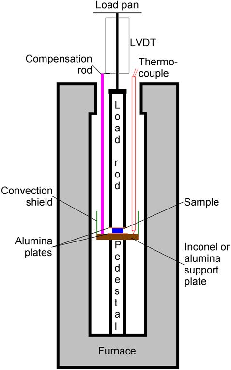
Figure 1: Schematic of the parallel plate viscometer
It is important to pay attention to the geometry of deformation during measurement. Figure 2 illustrates the extrema: either the glass sample shows a "perfect slip" on the substrates (i.e. the contact areas between sample and substrate increase, the sample remains a rectangular cylinder), or "no slip" where the contact areas to the substrates stay constant and the glass sample "bulges out". Varshneya [9] shows that superior results are obtained if no-slip condition is assumed using alumina substrates.

Figure 2: Perfect slip and no-slip conditions during parallel plate viscosity measurement
Following assumptions are further made:
- The viscous sample is incompressible,
- The flow is Newtonian,
- The sample does not completely fill the area between the substrates during testing,
- The sample remains cylindrically symmetric during flow.
Under these assumptions, the glass viscosity may be calculated from the sag rate through Equation (1):
![]()
where ![]() = glass viscosity in Poise or Pa
= glass viscosity in Poise or Pa![]() s;
M = applied load; g = gravity acceleration; h = sample height; V =
sample volume; dh/dt = deformation or sag rate;
s;
M = applied load; g = gravity acceleration; h = sample height; V =
sample volume; dh/dt = deformation or sag rate; ![]() = roughly estimated linear expansion coefficient; DT =
temperature change compared to room temperature. The term (1 +
= roughly estimated linear expansion coefficient; DT =
temperature change compared to room temperature. The term (1 + ![]()
![]()
![]() T) can be neglected for low expanding glasses.
T) can be neglected for low expanding glasses.
Using the parallel plate technique, it is possible to
measure viscosities in the glass softening range, log(![]() / Pa
/ Pa![]() s) = 4 to 10. At the lower end of the range, low
loads, large diameter samples, and heating rates up to maximal 5oC/min
may be needed. The heating rate should not be substantially lower than 1oC/min,
else some glasses may crystallize during measurement which can lead to
incorrect viscosity results.
s) = 4 to 10. At the lower end of the range, low
loads, large diameter samples, and heating rates up to maximal 5oC/min
may be needed. The heating rate should not be substantially lower than 1oC/min,
else some glasses may crystallize during measurement which can lead to
incorrect viscosity results.
Ball penetration viscometry
The ball penetration viscometry is described by Douglas et al. [12] and Brückner et al. [13]. A hard, incompressible, chemically inert sphere about 3 mm diameter is allowed to penetrate a flat specimen of glass. Again, the sag rate is measured with time. Following expression is used to calculate the viscosity:
![]()
with ![]() = glass viscosity in Poise or Pa
= glass viscosity in Poise or Pa![]() s;
M = applied load; g = gravity acceleration; L = penetration depth; dL/dt =
deformation or sag rate; R = sphere radius. It should be noted that this
equation is valid for small penetration only. The advantages of the ball penetration technique
lie in the simplicity of the method and the ease of the glass sample preparation.
Ball/spheres as indenting body are preferred over cylindrical rods or cones because,
in the latter case the friction depends on the penetration depth and viscosity
[13]. For chemical inertness, Brückner [13] recommended chromium nickel steel
up to 650oC. Polished alumina or zirconia balls may be used at
higher temperatures. The investigated material should have absolutely no
irregular inclusions (e.g. bubbles), because the sampled material volume is
generally very small. The ball penetration technique is suitable for
relatively high viscosities in the glass softening range (log(
s;
M = applied load; g = gravity acceleration; L = penetration depth; dL/dt =
deformation or sag rate; R = sphere radius. It should be noted that this
equation is valid for small penetration only. The advantages of the ball penetration technique
lie in the simplicity of the method and the ease of the glass sample preparation.
Ball/spheres as indenting body are preferred over cylindrical rods or cones because,
in the latter case the friction depends on the penetration depth and viscosity
[13]. For chemical inertness, Brückner [13] recommended chromium nickel steel
up to 650oC. Polished alumina or zirconia balls may be used at
higher temperatures. The investigated material should have absolutely no
irregular inclusions (e.g. bubbles), because the sampled material volume is
generally very small. The ball penetration technique is suitable for
relatively high viscosities in the glass softening range (log(![]() / Pa
/ Pa![]() s) = 8) up to the lower end of glass annealing (log(
s) = 8) up to the lower end of glass annealing (log(![]() / Pa
/ Pa![]() s) = 12).
s) = 12).
Fiber elongation viscometry
The fiber elongation viscometry is nased upon the Littleton
softening point determination and is described in ASTM C338 [14] and ISO 7884-3
[15]. For most glasses the Littleton softening point is at a viscosity of log(![]() / Pa
/ Pa![]() s) = 6.6, where high density lead, bismuth,
barium, and telluride glass compositions may show a slightly higher viscosity
at the Littleton softening point.
s) = 6.6, where high density lead, bismuth,
barium, and telluride glass compositions may show a slightly higher viscosity
at the Littleton softening point.
A 0.55 to 0.75 mm diameter glass fiber
is drawn. One end is fused to make a ball. The glass fiber is cut to 23.5 cm
length, and then suspended inside a specified furnace, which only covers the
top 10 cm [11, p 193-194]. The furnace is heated at a rate of 5oC/min.
The sagging of the lower end is sighted using a telescope and measured as a
function of time. When the glass fiber extends under its own weight, the temperature
when the rate of extension of the lower end is 1 mm/min corresponds to the
softening point viscosity. To measure higher viscosities, one may need to load
the glass fiber by placing weights in a pan attached to the lower end. Viscosities in
this manner have been measured to the practically high limit of about log(![]() / Pa
/ Pa![]() s) = 15.
s) = 15.
Comparison of viscometry techniques in the glass softening range
The parallel plate technique offers various advantages relative to the ball penetration and fiber elongation methods. The samples are easy to prepare and the sample size is small. It is not necessary to flame-work glass fibers that may possess altered surface compositions (e.g. alkali and boron depleted) which cause changes in the glass structure and viscosity. In addition, the parallel plate technique does allow viscosity measurements over a wider range than the ball penetration viscometry, especially at lower viscosities. In addition, through parallel plate viscometry the viscosity of a large and compact sample volume is tested, i.e., small bubbles do not have as a significant influence as when using the ball penetration or fiber elongation techniques. Therefore, the parallel plate viscometry may be considered most effective in the glass softening range.
Viscosity measurement in the glass transition range
In the glass transition range beam bending viscometers are used, as described in ISO 7884-4 [16] and ASTM C1350 [17]. - under construction -
References
[1] ISO 7884-1: Glass - Viscosity and viscometric fixed points, Part 1: "Principles for determining viscosity and viscometric fixed points", Edition 1998-02
[2] ASTM E220-02: "Standard Test Method for Calibration of Thermocouples by Comparison Techniques", 2002
[3] ASTM E230-03: "Standard Specification and Temperature-Electromotive Force (EMF) Tables for Standardized Thermocouples", 2003
[4] ISO 7884-2: Glass - Viscosity and viscometric fixed points, Part 2: "Determination of viscosity by rotation viscometers", Edition 1998-02
[5] ASTM C965-96: " Standard Practice for Measuring Viscosity of Glass Above the Softening Point", Reapproved 2002
[6] G. J. Dienes, H. F. Klemm: "Theory and Application of the Parallel Plate Plastometer"; J. Appl. Phys. 17 (1946), 458-471
[7] A. N. Gent: "Theory of the Parallel Plate Viscometer"; Br. J. Appl. Phys. 11 (1960), 85-88
[8] E. H. Fontana: A Versatile Parallel-Plate Viscometer for Glass Viscosity Measurements to 1000oC; Ceram. Bull. 49 [6] (1970), 594-597
[9] A. K. Varshneya, N. H. Burlingame, W. H. Schultze: "Parallel Plate Viscometry to Study Deformation-Induced Viscosity Changes in Glass"; Glastechn. Ber. 63K (1990), 447-459
[10] ASTM C1351M-96: "Standard Test Method for Measurement of Viscosity of Glass Between 104 Pa·s and 108 Pa·s by Viscous Compression of a Solid Right Cylinder", reapproved 2002
[11] A. K. Varshneya, "Fundamentals of Inorganic Glasses", Academic Press, Boston 1993
[12] R. W. Douglas, W. L. Amstrong, J. P. Edward, D. Hall: "A penetration viscometer"; Glass Tech., April 1965, vol. 6, no. 2, p 52-55
[13] R. Brückner, G. Demharter: "Systematic investigation of the use of penetration viscometers"; Glastechn. Ber., Jan. 1975, vol. 48, no. 1, p 12-18 (in German)
[14] ASTM C338-93: "Standard Test Method for Softening Point of Glass" (Reapproved 2003)
[15] ISO 7884-3: Glass - Viscosity and viscometric fixed points, Part 3: "Determination of viscosity by fibre elongation viscometer", Edition 1998-02
[16] ISO 7884-4: Glass - Viscosity and viscometric fixed points, Part 4: "Determination of viscosity by beam bending", Edition 1998-02
[17]
ASTM C1350M-96: " Standard Test Method for Measurement of Viscosity of
Glass Between Softening Point and Annealing Range (Approximately 108
Pa![]() s to Approximately 1013 Pa
s to Approximately 1013 Pa![]() s) by Beam Bending", Reapproved
2003
s) by Beam Bending", Reapproved
2003